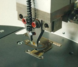
The Hot-Bar reflow is a selective soldering process where connect two pre-fluxed, solder coated parts by heating element, call a thermode, with proper temperature
to melt the solder.
Applying a pressure and contacting on the soldering target is necessary to melt the solder
and insure that components stay in place during cooling.
The regular Hot-Bar reflow process is to pre-print the solder paste on the PCB then go SMT reflow with other SMD components. After
that then stick the FPC on the board and melt the solder again through thermode to
connect the FPC on PC board.
In order to mount FPC on PCB, a thermal-conductor inside FPC to transfer heat from thermode to PCB to melt the printed solder
on PCB is necessary.
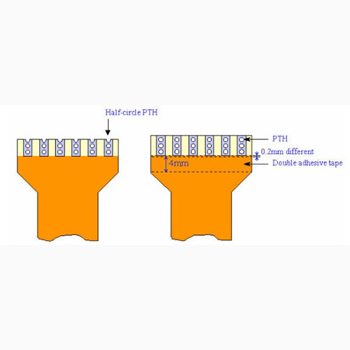
The common conductor inside FPC is building Plating Hole (PTH) on contact finger of FPC
as below sketch. Three PTHs on each contact finger are preferable. One half-circle via + two
circle vias can be acceptable if there is no space for three completed vias.
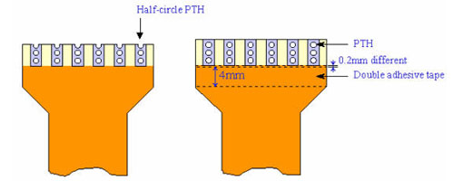
It is necessary to apply double adhesive to fix FPC on board during Hot-Bar reflow process. No body like to take the hot touch risk to hold FPC on PCB during Hot Bar
process. Two registration holes on the both left/right sides of PFC to hold the FPC during
Hot-Bar heating process is doable.
To summary the requirements for Hot-Bar FPC:
· 3 PTHs on Hot-Bar finger.
· Double adhesive at near side to stick flex cable on PCB before Hot Bar process. The thickness
should be less than 0.15mm and leave 0.2mm space from Hot-Bar terminal.
Hot-Bar PCB pattern size should be designed as below to prevent solder short between patterns
while thermode press down.
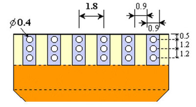
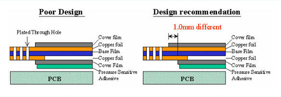
In order to prevent FPC from broken at solder finger edge. It is recommended to make different
cover films (polymide) with various length end to fix the stress concentration issue. Detail
recommended structure show as below.
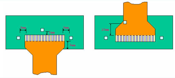
The recommended components distance from Hot-Bar land pattern:
·The minimum distance from components to front side of FPC is 2mm.
·The minimum distance from components to both sides of PCB is 3mm.
·The minimum distance from PCB edge to contact pads of FPC is 5mm.
(This 5mm is for double adhesive tape purpose)
·The minimum distance from components to contact pads under FPC is 10mm.
(This 10mm is for double adhesive tape fixing on PCB)